
Buyers often call a deeper mark at the beginning or end of a planed board “snipe.” That term is common in woodworking, but the mechanism on a hand-held electric planer should not be assumed to be identical to the roller and work-support behaviour of a benchtop thickness planer. With a handheld tool, a tilted sole, unsupported workpiece, poorly controlled entry or exit, blade alignment or excessive depth can all contribute to an uneven result. A product review should diagnose the pattern before deciding that the motor or depth dial is defective.
This is a buyer's diagnostic method for sample approval, not a how-to for untrained operators. Planer blades are hazardous even after a tool is switched off. Isolate power and follow the exact manual before inspection or adjustment. The aim is to separate material, setup, technique and tool causes with a repeatable test, then decide what the retail product needs to explain.
Define the defect and its location
Mark the board's direction of travel and photograph the full surface before cutting. After the pass, identify whether the defect occurs only at entry, only at exit, along one edge, or across the entire board. A short deeper patch at the end suggests a different investigation from a continuous tapered cut. A repeatable stripe in the same lateral position points elsewhere again. Avoid a one-word complaint code such as “uneven” if the pattern can be described more precisely.
The intended use matters. A door installer may need a controlled edge trim and should not accept a gouge that prevents proper fit. A rough site-carpentry application may have a different finish tolerance. Ask for the material, board length and width, grain, depth of material to remove and final fit requirement. The door-fitting workflow guide puts the cut into a real installation sequence.
Do not infer a product defect from a single pass on a short offcut held loosely in a vise. The board needs secure support, adequate length for the tool's front and rear soles, and a safe work position. If the product is marketed for narrow door edges or similar material, choose a representative sample rather than a broad bench board that conceals edge-control problems.
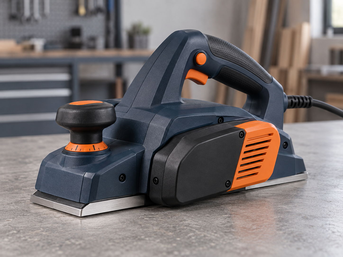
Caption: Marking the start, middle and exit of a pass helps distinguish an end gouge from a continuous tool fault.
Check the reference surfaces before blaming the cutter
With the tool disconnected or battery removed, a qualified technician can inspect the front and rear soles for damage, debris and obvious alignment issues using the manufacturer's method. Check that the depth adjustment moves as expected and that the zero position has been understood correctly. The depth-setting test guide explains why a dial number is not by itself a measured cut on every piece of timber.
Inspect blade condition and seating according to the tool's instructions. A chipped or unevenly installed blade can leave a ridge or asymmetric cut. Bosch's hand-planer manual illustrates the level of model-specific detail required for blade installation; it should not be copied as instructions for another planer. Record the actual blade type and revision in the sample sheet.
Look at the workpiece too. A bowed board or inconsistent clamping can change its relation to the planer. Mark the board's high spots and support points. A sample test is only meaningful if the piece remains stable through the cut. Do not ask an operator to hold a narrow board in one hand while planing with the other to demonstrate a retail use case.
Run controlled passes and vary one factor at a time
Use a competent operator, secured board, shallow setting appropriate to the exact tool and material, and the prescribed hand placement. Record the direction, depth setting, blade condition and any guide used. Make a first pass; measure or photograph the resulting profile. If the defect appears, repeat on a similar board while changing only one plausible cause: work support, entry and exit technique under the manual, blade condition, or guide alignment. Changing several variables at once may make the result better without revealing why.
The operator should observe how the tool transfers from front sole to rear sole contact during the pass. This is not an invitation to lift, tilt or force the planer; it is a way to understand whether the sample's design and instruction set support the intended workflow. If a qualified operator can achieve a consistent cut only by using a highly unusual manoeuvre, the retail offer may need clearer training or a different tool configuration.
Record the board profile at several points. A straightedge, caliper or fit gauge can be used when appropriate, but the method must be repeatable and suited to the customer's tolerance. “Looks flat” in a photograph may hide a small but important edge deviation. Conversely, an isolated mark outside the intended finished area may be commercially irrelevant. The buyer should establish acceptance criteria before seeing the result.
Mid-article sourcing CTA: Seeing uneven planer samples? Send the workpiece dimensions, defect location and blade configuration to discuss a controlled comparison.
Distinguish an end mark from other finish problems
Tear-out follows wood fibres and can vary with grain direction; an end gouge has a positional relationship to the start or finish of the pass. A repeated narrow ridge may align with a blade nick. Chatter or scalloping across the whole board could involve blade balance, feed, support or mechanical condition. The tear-out guide helps separate grain-related damage from a geometry problem. These descriptions are screening clues, not final diagnoses.
Ask whether the issue occurs on both sides of the cutting width. A deeper line on one side may prompt a check of blade alignment, guide position or operator tilt. If the symptom repeats across users and boards, the case for a tool or blade issue strengthens. If it disappears when the board is properly secured or the technique follows the manual, the product information may need improvement rather than the hardware.
Do not “repair” an apparent cut-quality issue by asking the factory to alter a safety-critical blade setting without an engineering review. Cutterhead and blade geometry belong to a designed system. The buyer should request a documented investigation and re-test on a labelled sample. Any change that affects the approved cut should be included in the production revision record.
Decide what the channel should promise
A trade distributor can provide a setup checklist and controlled sample data. A retail product page should say what the planer is intended to do, identify the supplied blade and guide, and give a clear path to the manual. It should not promise perfect flatness or “zero snipe” on all timber. Wood varies, and handling is part of the result. If the model has a feature intended to help with edge control, describe the exact component and demonstrate it on the approved sample.
The carton and product images should reflect the actual supplied guide, dust bag and blade type. A polished photograph of a door edge does not prove the packed configuration can reproduce the result. If the user needs a separate straightedge or jig for a precise fit, do not imply it is included unless it is. This is where a clear accessory list prevents post-sale disappointment.
Include replacement blade information. A consistent sample finish with new blades may deteriorate after wear; the customer needs a route to correct replacements. The blade replacement kit guide covers the item and instruction requirements that affect long-term cut quality.
Connect the diagnosis to factory and shipment checks
If cut quality is a defined acceptance item, establish a controlled test board and method for sample approval and relevant production checks. Record material, board dimensions, depth setting, blade ID, operator and acceptance tolerance. A factory inspector should not be asked to judge an unlabelled scrap board by eye. Separately check tool assembly, sole, blade seating, adjustment and accessories according to the engineering plan.
At pre-shipment inspection, verify that the production units carry the same blade type, guide, manual and carton information as the approved sample. The final inspection is not a substitute for controlling cutterhead or blade changes during production. The ToolViron quality overview can help map the checkpoints from sample to packed unit.
For safety context, OSHA's woodworking point-of-operation guidance stresses guarding, maintenance and de-energizing equipment before intervention. Its discussion spans woodworking equipment generally; apply the exact hand-planer manual and local rules to the model under review.
Caption: Illustrative range photography: blade and cut-quality decisions require a real sample.
A controlled comparison of two complaint boards
Imagine a distributor receiving two photographs labelled “planer makes uneven cuts.” In the first, a deeper patch appears only at the last few centimetres of a long door edge. In the second, a narrow raised line runs the full length of a board. Treating them as the same defect would waste time. The first calls for a review of support, entry/exit handling and sole contact under the manual. The second suggests checking blade condition and position, though material and setup must still be considered.
Ask the customer or service centre for the tool model and batch, installed blade type, timber, approximate depth and a photograph of the entire board. Do not ask an untrained person to expose the cutterhead or run a risky demonstration. A qualified technician can reproduce the symptom on safely secured, labelled material. If the end patch disappears with correct work support, the importer may need a clearer setup diagram rather than a motor change. If the continuous ridge appears across multiple boards and operators, blade or cutterhead investigation becomes more urgent.
The diagnostic report should use measured or clearly photographed locations: entry, middle and exit. If a straightedge shows an increasing taper, record direction and magnitude. If a guide was installed, note whether its setting was fixed. A verbal statement that “the cut is bad” cannot distinguish a local tool issue from a workpiece that was already bowed. Keep the original board where practical so another reviewer can check the observation.
The purchasing decision may be to accept the sample with improved instructions, request a blade alignment correction, reject a lot or run a new trial after a controlled component change. Each is a different action. A good quality process does not automatically blame technique; it tests that hypothesis alongside tool and material factors. That protects both the customer and the supplier from a premature conclusion.
Acceptance criteria that buyers can actually inspect
Define the product's intended cut tolerance and the material used for approval. For a door-fitting range, a small dimensional difference may matter more than a cosmetic scratch; for rough site trimming, the reverse might be true. Choose a measurement method the factory and buyer can repeat. Record depth dial position, actual removal and any required guide. If a sample trial finds a consistent deviation, state whether it is within the intended use and whether user instructions disclose the setup needed.
Require a blade-change record when a failed sample is reworked. The replacement blade's part number, seating method and test result should be linked to the unit, not lost in a note saying “fixed.” A new blade may improve the cut but reveal that production blades or installation checks need attention. If only one sample was reworked, inspect additional units before concluding the lot is controlled.
For shipment, give the inspector an approved sample and a practical checklist: blade ID, guide, sole condition, adjustment, manual revision and a defined sample cut if agreed. The inspection should not require subjective carpentry expertise without a test standard. The buyer should be able to explain both a pass and a failure from the recorded evidence.
Record the remedy as carefully as the defect
If a technician corrects an uneven cut by changing blade seating, retain the previous and revised measurements and note the part or procedure changed. If improved work support resolves an end mark, photograph that setup for the instruction review. This prevents a vague “fixed” note from hiding whether the factory must change its assembly process or the retailer must improve setup guidance. A repeatable remedy is more valuable than a one-off clean board.
Frequently asked questions
Is a deeper mark at the end always a defective planer?
No. Work support, handling, depth and blade setup can contribute. Reproduce the pattern on secured, labelled material with a qualified operator before assigning a cause.
Is handheld-planer snipe the same as thickness-planer snipe?
The word is used for deeper end cuts in both contexts, but the mechanisms can differ. Diagnose the actual handheld tool and workpiece rather than copying a thickness-planer remedy.
What does a continuous ridge usually indicate?
It may suggest a blade nick or seating issue, but this is only a clue. Inspect the blade safely and test another labelled board before concluding.
What should be recorded during sample approval?
Record board identity and support, cut direction, depth, blade ID, guide, operator, defect location, measurements and photographs. Keep the acceptance decision tied to the exact tool revision.
Conclusion
An uneven planer edge is a diagnostic problem, not a reason to guess at motor power. Describe the defect, control the board and pass, inspect the tool safely, then vary one factor at a time. A buyer can use the result to approve the product, correct the configuration or improve the user information without overstating what a handheld planer guarantees.
Send your requirements
Share the intended edge task, timber, defect pattern and target tolerance. ToolViron can discuss a planer sample review and configuration questions. Send your requirements to begin.
Images illustrate product and inspection topics; they are not documentary evidence of a specific ToolViron test or customer project. Confirm the exact model and market requirements before ordering.