
An electric planer can sound healthy and still leave a step, tapered cut or rough surface because its front base, rear base and cutter are not working together as intended. For a B2B buyer, a no-load motor test is therefore insufficient sample evidence. Geometry, blade setting, depth control and a representative cut should be reviewed as one system. The objective is not to turn a purchaser into a repair technician; it is to define a check the factory and buyer can repeat safely.
Makita's power-planer instruction manual explains model-specific blade setting and front-base placement for its tool. Another planer's blade system may differ. Always use the exact product manual and a qualified technician for any adjustment or service. This article outlines procurement questions and evidence boundaries, not a universal calibration method.
Understand the two bases and the cutter
The front base rides on material before it reaches the cutter and is typically adjusted to set the depth of cut. The rear base supports the tool on the newly cut surface. The blade or cutter must relate correctly to the rear base for an even pass. If these relationships are wrong, a buyer may see a step at the start or end of a board, an uneven width or chatter. The same symptom can also result from user feed, timber support or damaged blades.
Define the intended application first: door trimming, board flattening, edge preparation or site fitting. A planer positioned for narrow, shallow finishing passes should be tested differently from one sold for heavier stock removal. Record the acceptable surface outcome, workpiece species or grade, board dimensions and number of passes. An abstract “flatness” demand without an application can lead to over- or under-testing.
The planer depth-setting test addresses depth repeatability. Sole alignment is a related but distinct question: whether the two bases and cutter geometry produce the intended cut when the depth control is set correctly.
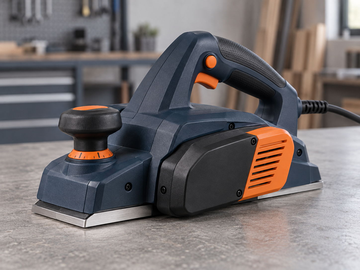
Caption: Front base, rear base and blade setting should be evaluated together.
Inspect the sample without operating it
With the tool isolated, check for shipping damage, loose base components, burrs, visibly uneven blade projection and a depth control that moves smoothly. Use the maker's inspection method; avoid placing fingers near the cutter or using an improvised gauge against a sharp blade. A straightedge or suitable reference can help assess the bases when applied by trained personnel, but the acceptance rule must name the surface, setting and method.
Check the full width of the sole. A narrow contact near one edge may reveal an issue not seen in the center. Inspect whether the front base remains stable when adjusted to several intended depths. If the sole has a chamfer groove, account for it in the measuring setup; a straightedge spanning a groove can mislead. Photograph the setup so the factory can reproduce it.
Confirm the installed blades or cutter assembly match the saleable specification. A promotional sample with premium blades and production kits with a different set will not give comparable finish results. Record blade type, lot, orientation and any allowable reversal according to the manual. The HSS versus carbide blade guide helps define the accessory choice.
Make a representative cut
Prepare a stable, secured workpiece in good condition. Note species or board type, grain direction, moisture context where relevant, width, initial surface and support. Set a shallow, model-appropriate depth. A trained operator should follow the manual's starting, feeding and stopping sequence. Do not attempt to correct a suspected geometric problem by forcing the planer through the timber.
Record the start, center and end of the pass. Look for a step at the beginning or end, uneven removal across width, visible ridges, chatter and blade marks. Measure thickness change or edge angle where the customer application requires it. Repeat on more than one sample and, if needed, with a verified fresh blade set to distinguish blade condition from tool geometry.
For a buyer, a useful result is not “it looks smooth.” It is “with the named board, blade, depth setting and feed method, the three sampled units produced the following finish and measured removal.” If one unit differs, investigate its base and blade setup before generalizing to the entire design. If all units differ from the customer requirement, the proposed model or method may be wrong.
Distinguish common symptoms
| Observed result | Questions to investigate |
|---|---|
| Step at the start | Front-base placement, initial support, blade/rear-base relation |
| Step at the exit | Rear-base support, workpiece support, feed technique |
| Ridge across width | Blade condition, blade setting, overlap between passes |
| One edge removes more | Sole, cutter and fence alignment; operator tilt |
| Chatter or torn surface | Blade sharpness, depth, feed, grain and workholding |
This table is only a triage map. It should lead to a controlled check, not an immediate instruction to adjust a blade. A buyer who changes several variables at once cannot tell which correction worked. Preserve the initial result and note each change.
Mid-article sourcing CTA: Reviewing a planer that leaves uneven cuts? Send the model, blade type, timber and sample photos for a controlled sample-check discussion.
Agree a factory control plan
Ask how the supplier sets and verifies the cutter and bases during assembly. Is there a fixture, a functional cut, a visual check or a combination? Which measurements are recorded, and what happens to an out-of-limit unit? A factory may not need to perform an elaborate woodworking trial on every product, but its control plan should address the characteristics the buyer approved.
The acceptance criteria should be written before mass production. State the blade set, depth setting, measuring instrument or test board, sample count and disposition rule. Use tolerances from product engineering and customer requirements, not arbitrary internet values. If the blade supplier, cutter drum or base casting changes, reassess the result under supplier change control.
At shipment inspection, the inspector can verify the model, blade type, depth control, base condition and a proportionate functional sample using the approved method. A visual check of the carton alone cannot confirm cut quality. Conversely, an ad hoc plane of scrap wood without a defined board or operator is weak evidence.
Make setup and service information consistent
The user manual should describe blade replacement and adjustment only to the extent the manufacturer permits for the user. A retailer should not publish a generic calibration tutorial for a different model. If qualified service is required, state the service route. The box contents must include any fence, wrench or other tool promised for approved maintenance.
If a customer reports uneven cutting, support should record board type, grain direction, blade condition, depth setting and whether the tool has been dropped. A bent base from a fall and a factory assembly issue demand different responses. Keep the returned tool and blades together during investigation so a service swap does not erase evidence.
Use complaint data by lot. A cluster of uneven-cut reports after a blade supplier revision suggests a different action from scattered user-technique questions. The electric planer feed-speed article can help support staff distinguish process from geometry.
Use a measurement system the factory can repeat
A straightedge check is useful only if the datum and tool position are controlled. The plan should say whether the front base is set to zero depth, where the straightedge contacts the rear base, which groove or opening must be avoided and how the tool is supported. A straightedge held by hand against a moving tool is not an acceptable shortcut. Qualified staff should perform non-powered checks with the cutter isolated.
Instrument condition matters. A bent straightedge or worn feeler gauge can produce an apparently precise but wrong result. Record instrument identity and check it periodically. If a supplier proposes a dedicated fixture, ask for a diagram and evidence that it matches the production-intent housing and base. A fixture made for the previous model may not locate the new casting correctly.
Run a short repeatability check. Have the same technician measure one unit several times after repositioning it, then ask another trained technician to repeat. If the numbers vary more than the proposed tolerance, refine the setup before using it as a lot-acceptance gate.
Distinguish planing defects on the board
A start step can emerge when the operator begins with too much pressure on the rear of the tool before the front base is fully supported. An exit step can appear when the front base leaves the board and the rear loses stable support. Those handling errors can mimic geometry defects. A controlled trial should include a correctly supported reference pass and document the operator method.
Across-width taper raises different questions: uneven blade projection, tool tilt or a workpiece that is not flat. A repeating ridge at the same position might be a chipped blade rather than a sole problem. Chatter can involve workholding, depth or blade sharpness. Photograph the surface under side light and label its position on the board, then change one variable at a time.
Do not allow a factory to “fix” every observation by adjusting the blade. If the base casting is out of specification, repeated blade compensation may create other problems and make service difficult. The root cause should match the observed geometry and be confirmed after correction.
Plan an acceptance decision for multiple units
Test more than the best showroom piece. Select units from different cartons or points in a pilot run and apply the same geometry and cut check. If one unit differs, inspect its assembly history. If all units show the same finish issue, question the design, instruction or acceptance criterion. Keep individual results; an average can conceal one clearly unacceptable tool.
Define defect severity before seeing the batch. A minor cosmetic sole mark outside the working surface is not the same as a blade-retention or cut-quality issue. Agree who can approve rework, how reworked units are retested and how the shipment inspector will identify them. A clean report should show the original failure and the verified correction.
Connect service parts to geometry
Replacement blades, holders and adjustment parts should have controlled part numbers. A local service center may need a gauge or model-specific setup procedure. If the importer cannot supply the right parts, a “serviceable” planer can become a replacement-only product. Discuss that commercial choice before launch.
When a customer returns a planer for uneven cutting, keep the original blades with the tool until diagnosis is complete. Swapping in a fresh blade immediately may solve the symptom but erase whether the issue was wear, installation or production. The service report should record both the as-received and after-service result.
A buyer release question
Before signing the sample approval, ask whether the cut result can be reproduced by a trained person who did not set up the demonstration. Give that person the manual, approved blade and test board specification. If the tool only performs well after undocumented adjustments by one engineer, the factory has not yet shown a controllable product. The release record should name those adjustments and move them into a verified process or remove the product from the proposed range.
This check also protects the supplier. A buyer who approves a one-off “best sample” without recording its setup may later reject production for failing an expectation that was never defined. A short, repeatable method is fairer to both sides than a verbal promise of smooth planing.
For a production follow-up, compare the accepted sample with tools from different cartons and dates. Note any recurring direction of cut error, loose adjustment or surface damage; a pattern may reveal a controllable assembly issue that a single best sample cannot show.
Frequently asked questions
Is a smooth no-load motor sound enough to approve a planer?
No. It confirms only part of the tool's function. A representative cut and geometry review are needed to see how the bases, blade and depth setting interact on a workpiece.
Does a step at the end always mean the sole is misaligned?
No. Poor workpiece support or a change in pressure as the front base leaves the board can cause a similar symptom. Repeat with a controlled setup before assigning a tool fault.
Can buyers set one universal blade-projection tolerance?
No. Blade and drum designs differ. Use the exact model's engineering specification and measuring method, then check that the resulting cut meets the intended application.
What should shipment inspection include?
Check the approved blades and accessories, base condition, depth-control operation and a sample cut under the agreed method. Keep observations linked to unit and lot identity.
Conclusion
A planer quality decision needs more than a spinning motor. Align the product requirement with a safe bench check and a representative cut, then keep blades, bases and user information consistent from sample to shipment. That makes defects easier to find and customer claims easier to resolve fairly.
Send your requirements
Share your intended planer application, blade configuration and finish expectations. ToolViron can discuss a sample and factory-control plan appropriate to the proposed model. Send your requirements to begin.

Caption: A recorded cut test connects the approved geometry to the customer's woodworking task.
Images illustrate product and inspection topics; they are not documentary evidence of a specific ToolViron test or customer project. Confirm the exact model and market requirements before ordering.